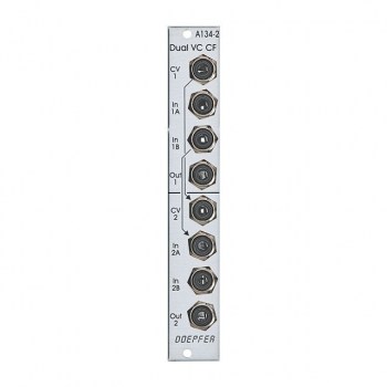
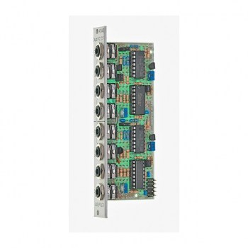
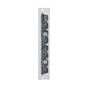
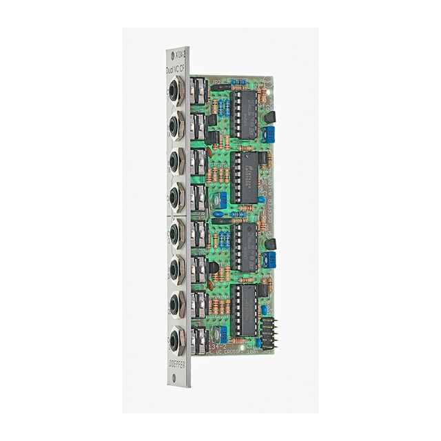
Module A-134-2 contains two identical voltage controlled crossfader units. Each unit has two voltage controlled amplifiers (VCAs) with opposite control behaviour available. The outputs of the VCAs are mixed together to obtain a common output. The behaviour of the control voltage inputs can be chosen with an internal jumper.
Symmetrical mode:
If the corresponding jumper is not set both VCAs of the crossfader have the same 50% amplification with zero CV. If the applied CV becomes positive the amplification of VCA1 increases and those of VCA2 decreases in the same way.
A negative CV has the opposite result. The CV voltage range to obtain the maximum/minimum positions of the crossfader is about -2.5....+2.5V. This mode is useful for bidirectional (i.e. positive and negative) control voltages, for example LFO or joy stick (adjusted to 0V CV in center position).
Asymmetrical mode:
If the corresponding jumper is set VCA1 is fully closed and VCA2 has full 100% amplification with zero CV. If the applied CV becomes positive the amplification of VCA1 increases and those of VCA2 decreases in the same way.
The CV voltage range to obtain the maximum/minimum positions of the crossfader is about 0....+5V. A negative CV has no function in this mode. This mode is useful for unidirectional (i.e. only positive) control voltages, for example ADSR, ribbon controller or Theremin control voltage.
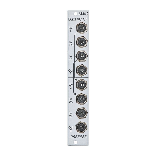
The CV input of the upper unit (CV1) is normalled to the CV input of the lower unit (CV2). I.e. if no plug is inserted to CV2 the CV input of the upper unit (CV1) also controls the lower unit.
The second signal input of the upper unit (In1B) is normalled to the first signal input of the lower unit (In2A). I.e. if no plug is inserted into In2A the signal In1B is used as the first signal input of the second unit.
As the inputs and outputs are DC coupled the module can be used for both audio and control voltage signal processing.
Manufacturer: DoepferTE / HP: 4Width (cm): 2,0Depth (cm): 4,5Type of Modul: Misc. Tools
Еще нет отзывов об этом товаре.
 Купить Doepfer A-134-2 Dual VC Crossfader - лучшая цена с доставкой по России в mustore.ru
  Купить Doepfer A-134-2 Dual VC Crossfader - лучшая цена с доставкой по России в mustore.ru
  Купить Doepfer A-134-2 Dual VC Crossfader - лучшая цена с доставкой по России в mustore.ru


