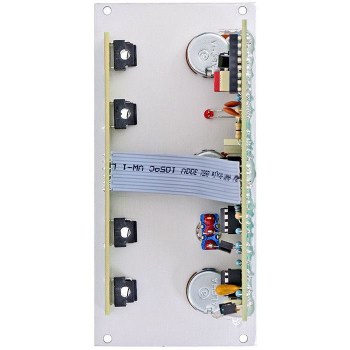
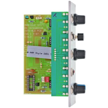
Analogue Systems RS-40 S&H/Clock/Noise
The RS-40 Noise Generator / Sample & Hold / Clock is really three separate ‘sub-modules’ that you can patch together to help generate classic Sample & Hold effects. But effects are far from the only uses for the sub-modules, and they can be patched into other RS Integrator modules for an even wider range of effects.
The noise and the clock provide suitable signals for the use with the S&H unit although they arent pre-patched for technical reasons.
The noise generatorproduces classic analog noise. A potentiometer sets its output level.
The sample and holdsection is very exact and can hold a value almost infinitely. The signal to be sampled is patched to the "ext src in" jack. The trigger that determins the point of sampling is inserted into the "ext clk in" socket. Alternatively you can trigger the S&H manually with the One Shot button if no trigger is inserted to the jack.
The clock generatorproduces a pulse wave between 0V and 10V. The frequency can be set in a range of 0.15Hz to 30Hz and is visualized with a LED.
Особенности устройства с сайта производителяNOISE GENERATOR
Some synthesisers offer 'noise' as an option on the main audio oscillators. This has a significant drawback: if your oscillators are acting as noise generators they are not outputting conventional waveforms. This can be very limiting and, for this reason, the Integrator's noise generator is provided on a separate module.
Unlike a standard oscillator, the Noise Generator requires no controls for its waveform or its frequency.
There is, therefore, just one control and one output. There is no input
- LEVEL:
The only method of controlling the Noise Generator is by adjusting the LEVEL knob. Turning this from its minimum to its maximum will cause the RS-40 to produce white noise in the range 0V (fully anticlockwise, and silent) to ±2.5V (fully clockwise).
- OUT:
The noise is output from the associated OUT socket.
SAMPLE AND HOLD
The RS-40 incorporates a highly stable S&H circuit that will sustain a constant voltage almost indefinitely.
Because it provides external inputs for the signal to be sampled and for the trigger, it can be used with any signals, not just a noise source and a clock. The inputs are the source signal input (E XT SRC IN) and the trigger input (EXT CLK IN). The output is... well, the output. The controls are an output level control
- EXT SRC IN:
This input accepts signals in the range 10V. These signals may be CVs or audio signals, and may be generated within the RS Integrator or presented by outside sources such as CDs, microphones, or other musical instruments. If the signal amplitude is too low for effective use as a source, you should use the Pre-Amp sub-module in the RS-70 to boost it to an appropriate level.
- EXT CLK IN:
This input will generate a trigger when it receives any positive-going waveform with a sharp leading edge. A pulse wave is the traditional signal to use for this, but almost any waveform will suffice - even sine waves above about 3Hz will provide a trigger. Note, however, that not all waves will cause the S&H to trigger in the same fashion.
- LEVEL:
The LEVEL control adjusts the range of voltages produced by the S&H. Think of it as a 'range' control: The source may exhibit variations of ±10V, but the LEVEL allows you to compress this to any range of voltages from 0V (fully anticlockwise, no effect is generated) to the full 10V (fully clockwise)
- ONE SHOT:
If no signal is presented to the EXT CLK IN socket, you can take a sample by pressing the ONE SHOT button. This will cause the S&H circuit to measure the instantaneous amplitude of the signal presented to the EXT S RC IN socket, and hold it until the next time you press the button.
- S&H OUT:
Sampled voltages, once scaled by the LEVEL control, are output here. The maximum signal amplitude is 10V.
CLOCK
A clock is simply another form of oscillator: one that produces a pulse wave at, typically, subsonic and low audio frequencies. It is most often used as a timer - for example, triggering envelopes and sample & hold circuits - but can also be used as a 'sync' or reset source for conventional audio oscillators and LFOs.
- FREQ:
You control the Clock frequency by adjusting the FREQ knob. Turning this from its minimum to its maximum will cause the RS-40 to produce clock pulses in the range 0.1Hz (fully anticlockwise) to approximately 30Hz (fully clockwise)
- OUT:
The level of the clock pulse wave is fixed at 10V.
- STATUS LED:
The status LED gives you a direct visual indication of clock rate.


